- Tempo Kapasitor (komponén) pikeun bahasan tipe husus.

Kapasitor:
SMD keramik di beulah kénca; SMD tantalum di beulah kénca handap;
through-hole tantalum di beulah katuhu luhur; through-hole éléktrolit di beulah katuhu handap. Kalolobaan babagian skala dina cm.
Kapasitor nyaéta parangkat
listrik nu bisa nyimpen
énérgi dina
médan listrik antara sapasang
konduktor nu jarakna deukeut (disebut 'pelat'). Nalika
voltase diterapkeun kana kapasitor,
muatan listrik kalayan gedé nu sarua, tapi polaritas atawa kutubna béda bakal diwangun dina unggal pelat.
Kapasitor digunakeun dina sirkuit listrik minangka alat panyimpen énérgi. Bisa ogé digunakeun keur misahkeun sinyal frékuénsi luhur jeung frékuénsi handap sarta ngajadikeunnana bisa dipigunakeun dina filter éléktronik.
Kapasitor kadang-kadang disebut kondénsator. Istilah ieu dianggep istilah baheula.
Sawangan
Kapasitor diwangun ku dua
éléktroda, atawa pelat konduktif, nu dipisahkeun ku
isolator
Kapasitansi kapasitor
Kapasitansi kapasitor (
C) nyaéta ukuran
muatan (
Q) nu kasimpen dina unggal pelat pikeun hiji
béda poténsial atawa
tegangan (
V) nu mucunghul antara pelat-pelat éta:

Dina hijian
SI, kapasitor mibanda kapasitansi
safarad lamun
sacoulomb muatan nyababkeun béda poténsial
savolt pikeun sakabéh pelat. Kusabab farad téh nyaéta hijian nu kacida gedéna, ajén kapasitor biasana diungkabkeun dina microfarad (µF), nanofarad (nF) atawa picofarad (pF).
The capacitance is proportional to the surface area of the conducting plate and inversely proportional to the distance between the plates. It is also proportional to the permittivityof the dielectric (that is, non-conducting) substance that separates the plates.
The capacitance of a parallel-plate capacitor is given by:
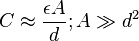
where ε is the
permittivity of the dielectric,
A is the area of the plates and
d is the spacing between them.
In the diagram, the rotated molecules create an opposing electric field that partially cancels the field created by the plates, a process called
dielectric polarization.
Enérgi nu kasimpen
As opposite charges accumulate on the plates of a capacitor due to the separation of charge, a voltage develops across the capacitor owing to the electric field of these charges. Ever-increasing work must be done against this ever-increasing electric field as more charge is separated. The
energy (measured in
joules, in
SI) stored in a capacitor is equal to the amount of work required to establish the voltage across the capacitor, and therefore the electric field. The energy stored is given by:
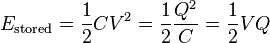
where V is the voltage across the capacitor.
The maximum energy that can be (safely) stored in a particular capacitor is limited by the maximum electric field that the dielectric can withstand before it breaks down. Therefore, all capacitors made with the same dielectric have about the same maximum energy density (Joules of energy per cubic meter).
Modél hidrolis
As electrical circuitry can be modeled by
fluid flow, a capacitor can be modeled as a chamber with a flexible
diaphragm separating the input from the output. As can be determined intuitively as well as mathematically, this provides the correct characteristics
- The pressure across the unit is proportional to the integral of the current
- A steady state current cannot pass through it but a pulse or alternating current can be transmitted
- the capacitance of units connected in parallel is equivalent to the sum of their individual capacitances
- applying too much pressure, above the maximum breakdown pressure, will destroy it.
Kapasitor dina sirkuit listrik
Sirkuit kalayan sumber DC
Electrons cannot easily pass directly across the dielectric from one plate of the capacitor to the other as the dielectric is carefully chosen so that it is a good insulator. When there is a current through a capacitor, electrons accumulate on one plate and electrons are removed from the other plate. This process is commonly called 'charging' the capacitor—even though the capacitor is at all times electrically neutral. In fact, the current through the capacitor results in the separation of electric charge, rather than the accumulation of electric charge. This separation of charge causes an electric field to develop between the plates of the capacitor giving rise to voltage across the plates. This voltage V is directly proportional to the amount of charge separated Q. Since the current I through the capacitor is the rate at which charge Q is forced through the capacitor (dQ/dt), this can be expressed mathematically as:
 | |
where
- I is the current flowing in the conventional direction, measured in amperes
- dV/dt is the time derivative of voltage, measured in volts per second.
- C is the capacitance in farads
|
|
For circuits with a constant (DC) voltage source, the voltage across the capacitor cannot exceed the voltage of the source. (Unless the circuit includes a switch and an inductor, as in
SMPS, or a switch and some diodes, as in a
charge pump). Thus, an equilibrium is reached where the voltage across the capacitor is constant and the current through the capacitor is zero. For this reason, it is commonly said that capacitors block DC current.
Sirkuit kalayan sumber AC
The capacitor current due to an
AC voltage or current source reverses direction periodically. That is, the AC current alternately charges the plates in one direction and then the other. With the exception of the instant that the current changes direction, the capacitor current is non-zero at all times during a cycle. For this reason, it is commonly said that capacitors 'pass' AC current. However, at no time do electrons actually cross between the plates, unless the dielectric breaks down or becomes excessively 'leaky'. In this case it would probably overheat, malfunction, burn out, or even fail catastrophically possibly leading to an explosion.
Since the voltage across a capacitor is the integral of the current, as shown above, with sine waves in AC or signal circuits this results in a phase difference of 90 degrees, the current leading the voltage phase angle. It can be shown that the AC voltage across the capacitor is in
quadrature with the AC current through the capacitor. That is, the voltage and current are 'out-of-phase' by a quarter cycle. The amplitude of the voltage depends on the amplitude of the current divided by the product of the frequency of the current with the capacitance, C.
Impedansi
The ratio of the
phasor voltage to the phasor current is called the
impedance of a capacitor and is given by:
where:

is the angular frequency,
C = capacitance in farads, and
While this relation (between the
frequency domain voltage and current associated with a capacitor) is always true, the ratio of the
time domain voltage and current
amplitudes is equal to

only for sinusoidal (AC) circuits in steady state.
Hence, capacitive reactance is the negative imaginary component of impedance. The negative sign indicates that the current leads the voltage by 90° for a sinusoidal signal, as opposed to the inductor, where the current lags the voltage by 90°.
The impedance is analogous to the
resistance of a
resistor. The impedance of a capacitor is
inversely proportional to the frequency—that is, for very high-frequency alternating currents the reactance approaches zero—so that a capacitor is nearly a
short circuit to a very high frequency AC source. Conversely, for very low frequency alternating currents, the reactance increases without bound so that a capacitor is nearly an open circuit to a very low frequency AC source. This frequency dependent behaviour accounts for most uses of the capacitor (see
"Applications", below).
Reactance is so called because the capacitor doesn't dissipate power, but merely stores energy. In electrical circuits, as in mechanics, there are two types of load, resistive and reactive. Resistive loads (analogous to an object sliding on a rough surface) dissipate the energy delivered by the circuit, ultimately by
electromagnetic emission (see
Black body radiation), while reactive loads (analogous to a spring or frictionless moving object) store this energy, ultimately delivering the energy back to the circuit.
Also significant is that the impedance is inversely proportional to the capacitance, unlike resistors and inductors for which impedances are linearly proportional to resistance and inductance respectively. This is why the series and shunt impedance formulae (given below) are the inverse of the resistive case. In series, impedances sum. In parallel, conductances sum.
Persamaan Laplace (widang s)
When using the
Laplace transform in circuit analysis, the capacitive impedance is represented in the
s domain by:
where C is the capacitance, and s (= σ+jω) is the complex frequency.
Kapasitor jeung arus nu pindah
The physicist
James Clerk Maxwell invented the concept of
displacement current, d
D/dt, to make
Ampere's law consistent with conservation of charge in cases where charge is accumulating as in a capacitor. He interpreted this as a real motion of charges, even in vacuum, where he supposed that it corresponded to motion of
dipole charges in the
ether. Although this interpretation has been abandoned, Maxwell's correction to Ampere's law remains valid.
Jaringan kapasitor
Susunan séri jeung paralél
Capacitors in a
parallel configuration each have the same potential difference (voltage). Their total capacitance (
Ceq) is given by:
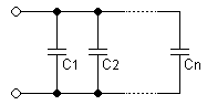

The reason for putting capacitors in parallel is to increase the total amount of charge stored. In other words, increasing the capacitance also increases the amount of energy that can be stored. Its expression is:

The current through capacitors in
series stays the same, but the voltage across each capacitor can be different. The sum of the potential differences (voltage) is equal to the total voltage. Their total capacitance is given by:
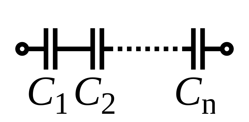

In parallel the effective area of the combined capacitor has increased, increasing the overall capacitance. While in series, the distance between the plates has effectively been increased, reducing the overall capacitance.
In practice capacitors will be placed in series as a means of economically obtaining very high voltage capacitors, for example for smoothing ripples in a high voltage power supply. Three "600 volt maximum" capacitors in series, will increase their overall working voltage to 1800 volts. This is of course offset by the capacitance obtained being only one third of the value of the capacitors used. This can be countered by connecting 3 of these series set-ups in parallel, resulting in a 3x3 matrix of capacitors with the same overall capacitance as an individual capacitor but operable under three times the voltage. In this application, a large
resistor would be connected across each capacitor to ensure that the total voltage is divided equally across each capacitor and also to discharge the capacitors for safety when the equipment is not in use.
Another application is for use of polarized capacitors in alternating current circuits; the capacitors are connected in series, in reverse polarity, so that at any given time one of the capacitors is not conducting.
Dualitas kapasitor/induktor
In mathematical terms, the ideal capacitor can be considered as an inverse of the ideal
inductor, because the voltage-current equations of the two devices can be transformed into one another by exchanging the voltage and current terms. Just as two or more inductors can be magnetically coupled to make a
transformer, two or more charged conductors can be electrostatically coupled to make a capacitor. The
mutual capacitance of two conductors is defined as the current that flows in one when the voltage across the other changes by unit voltage in unit time.
Panerapan
Capacitor symbols
| Capacitor | Polarized
capacitors | Variable
capacitor |
|---|
 |
|  |
Capacitors have various uses in electronic and electrical systems.
Panyimpenan énérgi
A capacitor can store electric energy when disconnected from its charging circuit, so it can be used like a temporary
battery. Capacitors are commonly used in electronic devices to maintain power supply while batteries are being changed. (This prevents loss of information in volatile memory.)
Capacitors are used in
power supplies where they smooth the output of a full or half wave
rectifier. They can also be used in
charge pumpcircuits as the energy storage element in the generation of higher voltages than the input voltage.
Capacitors are connected in parallel with the power circuits of most electronic devices and larger systems (such as factories) to shunt away and conceal current fluctuations from the primary power source to provide a "clean" power supply for signal or control circuits. Audio equipment, for example, uses several capacitors in this way, to shunt away power line hum before it gets into the signal circuitry. The capacitors act as a local reserve for the DC power source, and bypass AC currents from the power supply. This is used in
car audio applications, when a
stiffening capacitor compensates for the inductance and resistance of the leads to the
lead-acid car battery.
Koréksi faktor daya
Capacitors are used in
power factor correction. Such capacitors often come as three capacitors connected as a
three phase load. Usually, the values of these capacitors are given not in farads but rather as a
reactive power in volt-amperes reactive (VAr). The purpose is to counteract inductive loading from
electric motors and
fluorescent lighting in order to make the load appear to be mostly resistive.
Kopling sinyal
Because capacitors pass AC but block DC
signals (when charged up to the applied dc voltage), they are often used to separate the AC and DC components of a signal. This method is known as
AC coupling. (Sometimes
transformers are used for the same effect.) Here, a large value of capacitance, whose value need not be accurately controlled, but whose
reactance is small at the signal frequency, is employed. Capacitors for this purpose designed to be fitted through a metal panel are called feed-through capacitors, and have a slightly different schematic symbol.
Filter noise, motor starter, jeung snubber
When an inductive circuit is opened, the current through the inductance collapses quickly, creating a large voltage across the open circuit of the switch or relay. If the inductance is large enough, the energy will generate a spark, causing the contact points to oxidize, deteriorate, or sometimes weld together, or destroying a solid-state switch. A
snubbercapacitor across the newly opened circuit creates a path for this impulse to bypass the contact points, thereby preserving their life; these were commonly found in
contact breakerignition systems, for instance. Similarly, in smaller scale circuits, the spark may not be enough to damage the switch but will still
radiate undesirable
radio frequency interference(RFI), which a
filter capacitor absorbs. Snubber capacitors are usually employed with a low-value resistor in series, to dissipate energy and minimize RFI. Such resistor-capacitor combinations are available in a single package.
In an inverse fashion, to initiate current quickly through an inductive circuit requires a greater voltage than required to maintain it; in uses such as large motors, this can cause undesirable startup characteristics, and a motor starting capacitor is used to store enough energy to give the current the initial push required to start the motor up.
Capacitors are also used in parallel to interrupt units of a high-voltage
circuit breaker in order to equally distribute the voltage between these units. In this case they are called grading capacitors.
In schematic diagrams, a capacitor used primarily for DC charge storage is often drawn vertically in circuit diagrams with the lower, more negative, plate drawn as an arc. The straight plate indicates the positive terminal of the device, if it is polarized (see
electrolytic capacitor).
Pamrosésan sinyal
Sirkuit tala
Capacitors and
inductors are applied together in
tuned circuits to select information in particular frequency bands. For example, radio receivers rely on variable capacitors to tune the station frequency. Speakers use passive analog crossovers, and analog equalizers use capacitors to select different audio bands.

Panerapan séjén
Most capacitors are designed to maintain a fixed physical structure. However, various things can change the structure of the capacitor—the resulting change in capacitance can be used to sense those things.
Changing the dielectric: the effects of varying the physical and/or electrical characteristics of the dielectric can also be of use. Capacitors with an exposed and porous dielectric can be used to measure humidity in air.
Changing the distance between the plates: Capacitors are used to accurately measure the fuel level in
airplanes. Capacitors with a flexible plate can be used to measure strain or pressure. Capacitors are used as the
sensor in
condenser microphones, where one plate is moved by air pressure, relative to the fixed position of the other plate. Some
accelerometers use
MEMS capacitors etched on a chip to measure the magnitude and direction of the acceleration vector. They are used to detect changes in acceleration, eg. as tilt sensors or to detect free fall, as sensors triggering
airbag deployment, and in many other applications. Also some
fingerprint sensors.
Changing the effective area of the plates: capacitive touch switches
Pulsed power and weapons applications
Bahaya jeung kaamanan kapasitor
Capacitors may retain a charge long after power is removed from a circuit; this charge can cause shocks (sometimes fatal) or damage to connected equipment. For example, even a seemingly innocuous device such as a disposable camera flash unit powered by a 1.5 volt
AA battery contains a capacitor which may be charged to over 300 volts. This is easily capable of delivering an extremely painful, and possibly lethal shock.
Many capacitors have low
equivalent series resistance (ESR), so can deliver large currents into short circuits, and this can be dangerous. Care must be taken to ensure that any large or high-voltage capacitor is properly discharged before servicing the containing equipment. For safety purposes, all large capacitors should be discharged before handling. For board-level capacitors, this is done by placing a
bleeder resistor across the terminals, whose resistance is large enough that the leakage current will not affect the circuit, but small enough to discharge the capacitor shortly after power is removed. High-voltage capacitors should be stored with the terminals
shorted, since temporarily discharged capacitors can develop potentially dangerous voltages when the terminals are left open-circuited.
Large oil-filled old capacitors must be disposed of properly as some contain
polychlorinated biphenyls (PCBs). It is known that waste PCBs can leak into
groundwater under
landfills. If consumed by drinking contaminated water, PCBs are
carcinogenic, even in very tiny amounts. If the capacitor is physically large it is more likely to be dangerous and may require precautions in addition to those described above. New electrical components are no longer produced with PCBs. ("PCB" in electronics usually means
printed circuit board, but the above usage is an exception.) Capacitors containing PCB were labelled as containing "Askarel" and several other trade names.
Bahya alatan kapasitor tegangan luhur
Above and beyond usual hazards associated with working with high voltage, high energy circuits, there are a number of dangers that are specific to high voltage capacitors. High voltage capacitors may catastrophically fail when subjected to voltages or currents beyond their rating, or as they reach their normal end of life. Dielectric or metal interconnection failures may create arcing within oil-filled units that vaporizes dielectric fluid, resulting in case bulging, rupture, or even an
explosion that disperses flammable oil, starts fires, and damages nearby equipment. Rigid cased cylindrical glass or plastic cases are more prone to explosive rupture than rectangular cases due to an inability to easily expand under pressure. Capacitors used in RF or sustained high current applications can overheat, especially in the center of the capacitor rolls. The trapped heat may cause rapid interior heating and destruction, even though the outer case remains relatively cool. Capacitors used within high energy capacitor banks can violently explode when a fault in one capacitor causes sudden dumping of energy stored in the rest of the bank into the failing unit. And, high voltage vacuum capacitors can generate soft X-rays even during normal operation. Proper containment, fusing, and preventative maintenance can help to minimize these hazards.
Sajarah

Various types of capacitors. From left: multilayer ceramic, ceramic disc, multilayer polyester film, tubular ceramic, polystyrene (twice: axial and radial), electrolytic. Major scale divisions are cm.
In October
1745,
Ewald Georg von Kleist of
Pomerania invented the first recorded capacitor: a glass jar coated inside and out with metal. The inner coating was connected to a rod that passed through the lid and ended in a metal sphere. By having this thin layer of glass insulation (a dielectric) between two large, closely spaced plates, von Kleist found the
energy density could be increased dramatically compared with the situation with no insulator.
In January
1746, before Kleist's discovery became widely known, a Dutch physicist
Pieter van Musschenbroek independently invented a very similar capacitor. It was named the
Leyden jar, after the University of
Leyden where van Musschenbroek worked. Daniel Gralath was the first to combine several jars in parallel into a "battery" to increase the total possible stored charge.
The earliest unit of capacitance was the 'jar', equivalent to about 1
nF.
Early capacitors were also known as
condensers, a term that is still occasionally used today. It was coined by
Volta in
1782 (derived from the Italian
condensatore), with reference to the device's ability to store a higher density of electric charge than a normal isolated conductor. Most non-English languages still use a word derived from "condensatore", like the French
"condensateur", the German or Polish
"Kondensator", or the Spanish
"condensador".


 is the capacitive
  is the

